OMB 451UNI
OMB 451UNI
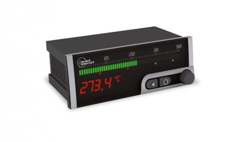
UNIVERSAL BARGRAPH - 50 LED with Display
The OMB 451 model series are panel programmable three-color bargraphs with auxiliary display and adjustable LCD scale. The OMB 451UNI type is a multifunction instrument with the possibility of configuration for 8 various input options, easily configurable in the instrument menu.
The instrument is based on a single-chip microcontroller with a multichannel 24-bit sigma-delta converter, which secures high accuracy, stability and easy operation of the instrument.
-
horizontal bargraph - 50 LED with display and LCD scale
-
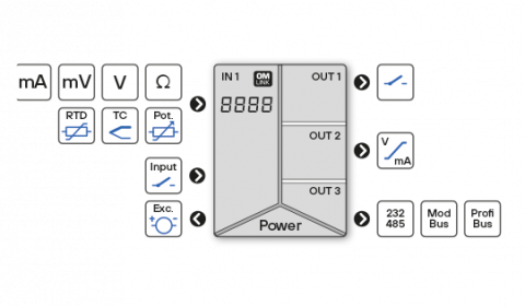
multifunction input (DC, PM, RTD, T/C, DU)
-
digital filters, tare, linearization
-
size of DIN 160 x 60 mm
-
POWER SUPPLY 10…30 V AC/DC or 80…250 V AC/DC
Options
-
comparators
-
data output
-
analog output
-
measured value record
Input
DC
Range
menu selectable
±60 mV
> 100 MOhm
Input U
±150 mV
> 100 MOhm
Input U
±300 mV
> 100 MOhm
Input U
±1200 mV
> 100 MOhm
Input U
PM
Range
menu selectable
0…20 mA
< 400 mV
Input I
4…20 mA
< 400 mV
Input I
±2 V
1 MOhm
Input U
±5 V
1 MOhm
Input U
±10 V
1 MOhm
Input U
±40 V
1 MOhm
Input U
OHM
Range
selectable in the menu with automatic change of the range
0…100 Ohm
0…1 kOhm
0…10 kOhm
0…100 kOhm
0…100 Ohm
0…1 kOhm
0…10 kOhm
0…100 kOhm
Connection
2, 3 or 4-wire
RTD
Type
menu selectable
EU > 100/500/1 000 Ohm s 3 850 ppm/°C
-50°…450°C
RU > 50 Ohm s 3 910 ppm/°C
-200°…1 100°C
RU > 100 Ohm s 3 910 ppm/°C
-200°…450°C
US > 100 Ohm s 3 920 ppm/°C
-50°…450°C
Connection
2, 3 or 4-wire
Ni
Type
menu selectable
Ni 1 000/10 000 s 5 000 ppm/°C
-50°…250°C
Ni 1 000/10 000 s 6 180 ppm/°C
-50°…250°C
Connection
2, 3 or 4-wire
Cu
Type
menu selectable
Cu 50/100 with 4 260 ppm/°C
-50°…200°C
Cu 50/100 with 4 280 ppm/°C
-200°…200°C
Connection
2-, 3-, or 4-wire
T/C
Type
selecmenu selectable
J (Fe-CuNi)
-200°…900°C
K (NiCr-Ni)
-200°…1 300°C
T (Cu-CuNi)
-200°…400°C
E (NiCr-CuNi)
-200°…690°C
B (PtRh30-PtRh6)
300°…1 820°C
S (PtRh10-Pt)
-50°…1 760°C
R (Pt13Rh-Pt)
-50°…1 740°C
N (Omegalloy)
-200°…1 300°C
L (Fe-CuNi)
-200°…900°C
DU
Range
Configuration is performed in two steps:
| 1. | setting numerical value for the beginning and end of the potentiometer range |
| 2. | slider position calibration for the beginning and end of the potentiometer runway |
Potentiometer power supply
2 VDC/6 mA, potentiometer resistance > 500 Ohm
Expansion "A" (DC ranges)
Range
menu selectable
±0,1 A
<300 mV
Input I
±0,25 A
<300 mV
Input I
±0,5 A
<300 mV
Input I
±1 A
<30 mV
Input I
±5 A
<160 mV
Input I
±100 V
20 MOhm
Input U
±250 V
20 MOhm
Input U
±500 V
20 MOhm
Input U
Expansion "B" 3x PM
Range
menu selectable
0…20 mA
<400 mV
Input 2, 3, 4 - I
4…20 mA
<400 mV
Input 2, 3, 4 - I
±2 V
1 MOhm
Input 2, 3, 4 - U
±5 V
1 MOhm
Input 2, 3, 4 - U
±10 V
1 MOhm
Input 2, 3, 4 - U
±40 V
1 MOhm
Input 2, 3, 4 - U
External inputs
Number
3 inputs, on contact
Functions
| OFF | No function |
| HOLD | Stopping measurement (option: Display - Analog output - Limits) |
| LOCK | Blocking front panel keys |
| BLOK.K. | Blocking front panel keys |
| B.HESL. | Blocking access to the LIGHT/PROFI menu |
| TARA | Tare activation |
| NUL. M.M. | Resetting Min/Max. value |
| ULOZ | Data record activation (extention of RTC/FAST) |
| NUL. PA. | Resetting memory (extention of RTC/FAST) |
| KAN. A | Value display "Channel A" |
| FIL. A | Value display "Channel A" after processing by a digital filter |
| MAT. FN. | Value display "Mathematical function" |
| PREP. | Gradual or BCD switching of the channels |
Projection
Display range
2x 50 LED
upper line displays the input value of the lower set limit
upper line displays the input value of the lower set limit
Bar colour
red/green/orange
Secondary display
-99999…999999, single-coloured 7-segment LED
Display height
9,1 mm
Display colour
red, green
Scale
LCD illuminated and freely programmable
Signalizing LED
| T | Tare (green) |
| M | Min./Max. value (green) |
| A, B, C, D | Channels A, B, C, D (orange) |
Description
the last two digits of the display can be used to display measured variables
Decimal point
menu adjustable - fixed or floating
Display brightness
menu adjustable
Displayed values
| Kan A | Value from channel A |
| Fil. A | Value from channel A after digital filter adjustment |
| Mat. Fn. | Value of mathematical function |
| Max. | Maximum value |
| Min. | Minimum value |
Settings
Control
The instrument is controlled and set by two buttons and a turning knob located on the front panel
Selected functions can also be controlled via external inputs
Selected functions can also be controlled via external inputs
Menu
| LIGHT | contains only items necessary for basic device settings with password access |
| PROFI | Full device settings with password access |
| USER | User menu of any item, selected from LIGHT/PROFI. Access without password. |
Optional functions
Buttons "Left", "Up", "Down", "Enter" can be assigned additional optional features
| ZAKAZ | button has no function |
| NUL. M.M. | Resetting Min/Max vaslues |
| NUL. TA. | Tare reset |
| MENU | Direct access to the selected menu item |
| DOC. H. | Temporary projection of selected values |
| PREP. 1 | Switching channels on display |
| ULOZ | Starting recording of the measured data into device memory |
| NUL. PA. | Resetting memory of the measured data |
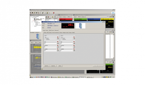
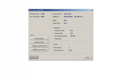
OM Link
Company communication interface for operation, setting and update of device firmware
OM Link program is also designed for visualization and filing of meas. values from more instruments
OM Link program is also designed for visualization and filing of meas. values from more instruments
Instrument accuracy and functionality
Temperature coefficient
50 ppm/°C
Accuracy
±0,1 % of range + 1 digit
±0,15 % of range + 1 digit (RTD, T/C)
(for projection 9999 and 5 measur./s)
±0,15 % of range + 1 digit (RTD, T/C)
(for projection 9999 and 5 measur./s)
Accuracy of cold junction measurement
±1,5°C
Rate
0,1…40 measur./s
Overload capacity
2x; 10x (t < 30 ms) - not for > 250 V and 5 A
Resolution (RTD, T/C)
1°C, 0,1°C, 0,01°C
Wire compensation (RTD, OHM)
< 30 Ohm
Cold junction compensation
adjustable -20°…99°C, automatic
Linearization
linear interpolation in 50 points (only via OM Link)
Digital filters
| arithmetic mean | from 2…100 measurements |
| floating mean | from 2…30 measurements |
| exponential mean | from 2…100 measurements |
| rounding | setting projection step for display |
Functions
| Tare | designed to reset display on non-zero input signal |
| Min/max value | registration of min./max. value achieved during measurement |
| Peak value | display shows only max. or min. values |
Math. functions
polynom, 1/x, logarithm, exponential, power, root
Math. operations between inputs
sum and quotient
Data record
Measured data recording into the memory
Not available in combination with with the data output MODBUS
| RTC | period - 1 s…1 day, time-date-display value, < 266k data, 15 ppm/°C |
| FAST | 40 records/s, display value, < 8k data |
Watch-dog
reset after 400 ms
Calibration
at 25°C and 40 % r.h.
Comparators
Type
Digital, menu adjustable, contact connect. < 30 ms
Mode
| Hysteresis | switch. point, hysteresis band "Mez ± 1/2 Hys." and time (0 ... 99.9 s) determ. switching delay |
| From-To | output interval ON and OFF |
| Dose | period, its multiples and time (0 ... 99.9 s), during which the output is active |
Output
1x relay, switch-over contact (250 VAC/50 VDC, 3 A)
2x relay, switch-over contact (250 VAC/50 VDC, 3 A)
3x relay, switch-over contact (250 VAC/50 VDC, 3 A)
4x relay, switch-over contact (250 VAC/50 VDC, 3 A)
2x open collector (30 VDC/100 mA)
4x open collector (30 VDC/100 mA)
2x relay, switch-over contact (250 VAC/50 VDC, 3 A)
3x relay, switch-over contact (250 VAC/50 VDC, 3 A)
4x relay, switch-over contact (250 VAC/50 VDC, 3 A)
2x open collector (30 VDC/100 mA)
4x open collector (30 VDC/100 mA)
Data outputs
Protocol
ASCII, MESSBUS, MODBUS - RTU, PROFIBUS DP
Data format
8 bits + no parity + 1 stop bit (ASCII)
7 bits + even parity + 1 stop bit (Messbus)
7 bits + even parity + 1 stop bit (Messbus)
Rate
600…230 400 Baud
0,0096…12 MBaud (PROFIBUS)
0,0096…12 MBaud (PROFIBUS)
RS 232
isolated
RS 485
isolated, addressing max. 31 instruments
Analogue outputs
Type
Isolated, programmable with a 16-bit D / A converter, type and range are menu selectable
Temperature coefficient
15 ppm/°C
Nonlinearity
±0,1 % of range
Rate
response to value change < 1 ms
Ranges
0...2 V, 0...5 V, 0...10 V, ±10 V, 0...5 mA, 0...20 mA, 4...20 mA
Compensation
600 Ohm/12 V, 1 000 Ohm/24 V
Error state
at range of 4...20mA
error message indication (<3.0 mA)
Detection of current loop interruption
error message indication (<3.0 mA)
Detection of current loop interruption
Sensor excitation
Adjustable
5…24 VDC/max. 1,2 W
Power supply
Power supply
10…30 V AC/DC, ±10 %, PF > 0,4, I < 40 A/1 ms, isolated
80…250 V AC/DC, ±10 %, PF > 0,4, I < 40 A/1 ms, isolated
80…250 V AC/DC, ±10 %, PF > 0,4, I < 40 A/1 ms, isolated
Current draw
< 15,5 W/15,5 VA
Power supply protection
Power supply is protected by a fuse inside the instrument
Operating conditions
Connection
connector terminal board, cable section < 1,5/2,5 mm2
Stabilization period
within 15 minutes after switch on
Operating temperature
-20°…60°C
Storage temperature
-20°…80°C
Protection class
IP64 (front panel only)
El. safety
EN 61010-1, A2
Dielectric strength
4 kVAC within 1 min. between pow. supply and input
4 kVAC within 1 min. between pow. supply and data/anal. output
4 kVAC within 1 min. between input and relay output
2,5 kVAC within 1 min.between input and data/anal. output
4 kVAC within 1 min. between pow. supply and data/anal. output
4 kVAC within 1 min. between input and relay output
2,5 kVAC within 1 min.between input and data/anal. output
Insulation resistance
for polution degree II, measuring cat. III.
| power supply | 670 V (ZI), 300 V (Di)* |
| input, output, PN | 300 V (ZI), 150 V (Di)* |
EMC
EN 61326-1
Seismic capacity
IEC 980: 1993, par.6
SW validation
Compliance with IEC 62138, 61226, class B, C
Mechanical properties
Material
Noryl GFN2 SE1, non-inflammable UL 94 V-I
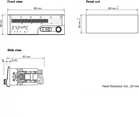
Dimensions
160 x 60 x 80 mm (w x h x d)
Panel cutout
150 x 50 mm (w x h)
Images
Dimensions and installation
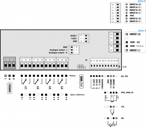
Connection
Datasheets
User manuals
| File name | File type | Version | Language | Download |
|---|---|---|---|---|
|
Operating instructions OMProfi
Návod OMProfi
|
PDF
|
2020.3 |
|
Download |
| Návod OMB450UNI |
PDF
|
2020.4.0 | cs | Download |
|
Operating instructions OMProfibus
Návod OMProfibus
|
PDF
|
2014.2.1 |
|
Download |
| Návod OMProfibus |
PDF
|
2014.2.0 | cs | Download |
|
Operating instructions OMProfibus
Návod OMProfibus
|
PDF
|
2010.1.2 |
|
Download |
| Návod OMProfibus |
PDF
|
2007.1.0 | cs | Download |
| Operating instructions OMProfibus |
PDF
|
2010.1.1 | en | Download |
|
Operating instructions OMB450UNI
Návod OMB450UNI
Operating instructions OMB450UNI
|
PDF
|
2013.3.0 |
|
Download |
| Návod OMB450UNI_B |
PDF
|
2010.1.0 | cs | Download |
Application notes
| File name | File type | Version | Language | Download |
|---|---|---|---|---|
| Application note Protocol MODBUS description |
PDF
|
2006.01 | en | Download |
| Application note protokol MODBUS popis |
PDF
|
2021.01 | cz | Download |
Certificates
| File name | File type | Version | Language | Download |
|---|---|---|---|---|
|
Certificate EU_Declaration_OMB451
Certifikát EU_Prohlaseni_OMB451
|
PDF
|
2022 |
|
Download |
|
Certificate Declaration_17050_OMB451
Certifikát Prohlaseni_17050_OMB451
|
PDF
|
2022 |
|
Download |
|
Certificate Seismic_test_OMB45xUNI
Certifikát Seizmicka_zkouzka_OMB45xUNI
|
PDF
|
2008 |
|
Download |
Firmware
| File name | File type | Version | Language | Download |
|---|---|---|---|---|
| OMB451UNI 77-502 |
HEX
|
2015 | xx | Download |
Software
| File name | File type | Version | Language | Download |
|---|---|---|---|---|
|
GSD OM-Profibus
GSD OM-Profibus
|
ZIP
|
2020 |
|
Download |
| GSDML OM-Profinet |
ZIP
|
2020.2.33 | xx | Download |
ISOLATED TRANSDUCER • USB < > OM INSTRUMENTS
Small compact transducer OM LINK USB with cable ensures safe and comfortable galvanically isolated connection between your computer and ORBIT MERRET instruments.